
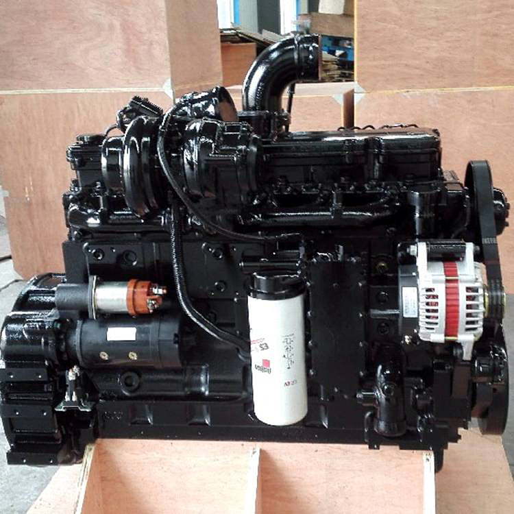
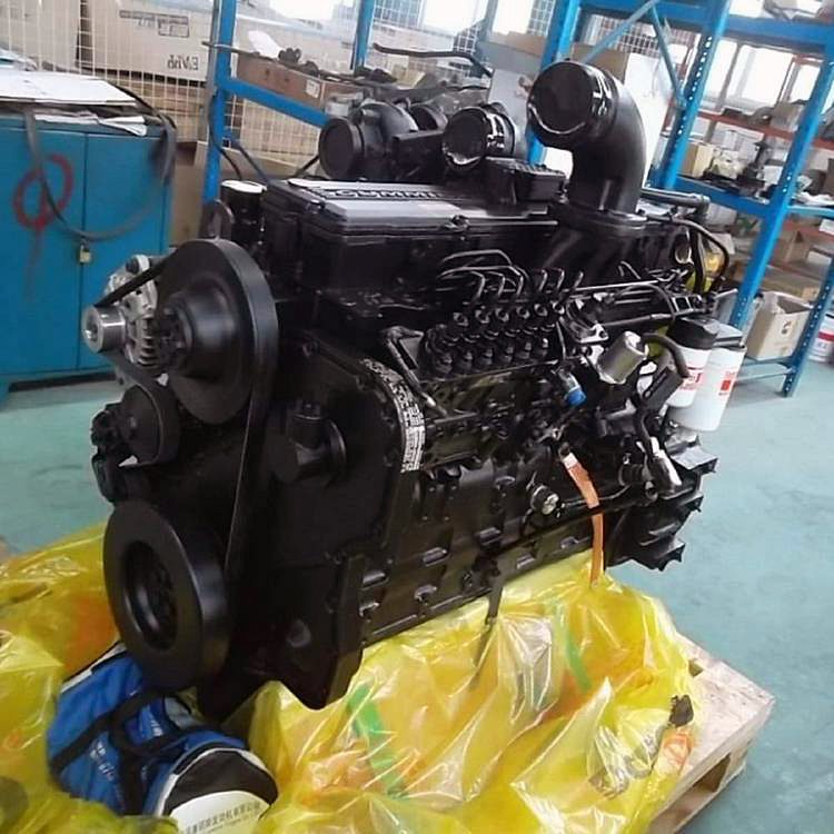
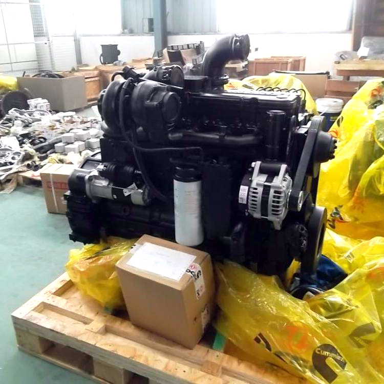
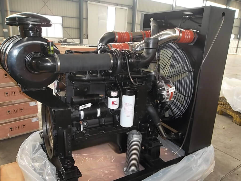
DCEC Cummins 6LTAA8.9-C360 Industrial Application Engine
| Engine Model | 6LTAA8.9-C360 |
| Rated Power / Speed: | 340 HP @ 2200 RPM |
| Peak Torque: | 1268 N·m @ 1000 RPM |
| Type | 6 Cylinders, in Line |
| Fuel System | BYC P7100 Pump RSV Mechanical Governor |
| Aspiration | Turbocharged & Air-Air Intercooler |
| Displacement | 8.9 L |
| Bore * Stroke | 114 mm * 145 mm |
| Packing Size (L * W * H) | 778 mm * 634 mm * 912 mm |
| Lead Time: | 5-15 Working Days |
General Infomation of DCEC 6LTAA8.9-C360 Industrial Engine
| General Infomation of DCEC 6LTAA8.9-C360 Industrial Engine | |||
| Engine Model | 6LTAA8.9-C360 | Curve & Datasheet | FR92929 |
| Compression Ratio | 16.6 : 1 | Displacement | 8.9 L |
| Advertised Power | 354 HP @ 2200 RPM | Bore * Stroke | 114 mm * 145 mm |
| Peak Torque | 1400 N·m @ 1400 RPM | Aspiration | Turbocharged & Air-Air Intercooler |
| Fuel System | BYC P7100 Pump / RSV Mechanical Governor | Cylinders | 6 Cylinders, in Line |
| Engine Wet Weight | 650 kg | Basic Engine(L * W * H) | N/A |
| Installation Data of DCEC 6LTAA8.9-C360 Industrial Engine | |||
| Moment Of Inertia Of Rotating Components (No Flywheel) | 0.72 kg·m² | ||
| Center Of Gravity From Front Face Of Block | 427 mm | ||
| Center Of Gravity Above Crankshaft Centerline | 163 mm | ||
| Maximum (Static) Bending Moment At Front Support Mounting Surface | 495 N.m | ||
| Maximum (Static) Bending Moment At Side Pad Mounting Surface | 250 N.m | ||
| Maximum (Static) Bending Moment at Rear Face of Block | 1356 N.m | ||
| Moment of Inertia of Complete Engine— Roll Axis | 29.8 kg·m² | ||
| Moment of Inertia of Complete Engine— Pitch Axis | 76.8 kg·m² | ||
| Moment of Inertia of Complete Engine— Yaw Axis | 66.9 kg·m² | ||
| Maximum Overspeed Capability | 3150 RPM | ||
| Crankshaft Thrust Bearing Load Limit—Maximum Intermittent | 5338 N | ||
| Crankshaft Thrust Bearing Load Limit—Maximum Continuous | 2670 N | ||
| Performance Data of DCEC 6LTAA8.9-C360 Industrial Engine | |||
| Minimum Idle Speed | 800 RPM | ||
| Maximum Speed Adjustment Speed (10% Rated Load) | 2400 RPM | ||
| Nominal Governor Regulation | ≤8% | ||
| Maximum Altitude Allowed for Continuous Operation | 2200 m | ||
| Maximum Torque Available At Closed Throttle Low Idle Speed | 700 N.m | ||
| Throttle Handle Angle – High Idle | 90 ± 10° Deg | ||
| Throttle Handle Angle – Low Idle | 70 ± 10° Deg | ||
| Throttle Handle Angle – Rotation Angle | 20 ± 5° Deg | ||
| Throttle Angle at Engine Shutdown – Engine Work | 42 ± 5° Deg | ||
| Throttle Angle at Engine Shutdown – Engine Shutdown | 340 ± 5° Deg | ||
Performance Data of DCEC 6LTAA8.9-C360 Industrial Engine
| Engine Performance Data Rated Power of DCEC 6LTAA8.9-C360 Industrial Engine | |||||
| Rated Power | Torque Peak | Rated Power | Torque Peak | ||
| Engine Speed | 2200 RPM | 1400 RPM | Exhaust Gas Temperature | 490 °C | 440 °C |
| Gross Power Output | 264 kW | 205 kW | Heat Rejection to Ambient | N/A | N/A |
| Torque | 1146 N.m | 1400 N.m | Heat Rejection to Coolant | N/A | N/A |
| Intake Manifold Pressure | 176 kPa | 180 kPa | Heat Rejection to Fuel | N/A | N/A |
| Friction Horsepower | N/A | N/A | Engine Coolant Flow | N/A | N/A |
| Turbo Comp. Outlet Pressure | 373 L/s | 261 L/s | External Cooling Circuit Resistance | N/A | N/A |
| Intake Air Flow | 954 L/s | 623 L/s | Altitude Limitations-Intermittent | N/A | N/A |
| Exhaust Gas Flow | 681 L/s | 467 L/s | Altitude Limitations-Continuous | N/A | N/A |
| Turbo Comp. Outlet Temperature | 170 ℃ | 160 ℃ | Steady State Smoke | 1.3 FSN | 2.2 FSN |
Advantages of DCEC 6LTAA8.9-C360 Industrial Engine
The DCEC 6LTAA8.9 series The electronic industrial engine is designed to comply with multiple EU emission standards (Stage III, IV, and V). The primary differences between the 30/40/50 models come from after-treatment configurations and ECU calibration, rather than changes to the engine’s mechanical structure. Below is a clear breakdown:
1. Emission Standards & Model Designations
30 / 40 / 50 series correspond to EU Stage III, Stage IV, and Stage V emission compliance.
All models share the same core engine platform. To meet higher emission requirements, manufacturers implement the following upgrades:
- After-treatment systems: Depending on the emission stage, the engine integrates components such as SCR systems, DOCs, or DPFs.
- ECU programming: Engineers adjust ECU software to control combustion, fuel injection, and exhaust treatment for optimal emissions performance.
2. Key Differences Between Emission Stages
- Stage III: Uses relatively simple emission control solutions and minimal exhaust after-treatment.
- Stage IV / Stage V: Employs advanced after-treatment systems (such as SCR and DPF) along with more sophisticated ECU calibrations to meet stricter NOx and particulate matter limits.
3. Availability & Technical Support
- Unlisted models: Contact the BLSH sales team to obtain detailed specifications or discuss customized configurations.
- Product updates: Visit EMAC’s official website regularly to stay informed about the latest product releases and specification updates.
4. Why This Design Approach Matters
- Regulatory compliance: The engine platform supports different regional regulations, including EU and North American standards.
- Engineering flexibility: A unified engine architecture simplifies equipment integration, while modular after-treatment systems allow manufacturers and operators to adapt to future emission requirements.
For specific applications, unlisted variants, or detailed technical documentation, reach out to BLSH’s sales or engineering team for tailored support and expert guidance.